
Retractable roofs · Engineering
How it works.
A retractable roof is three engineered systems delivered together: a fixed steel frame, a cover, and a mechanical movement system. Here is how they fit, from the membrane down to the ground.
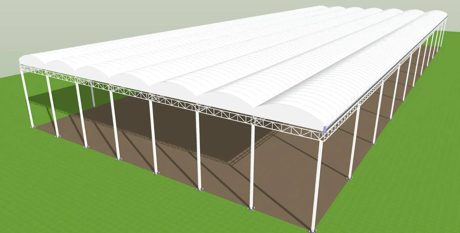
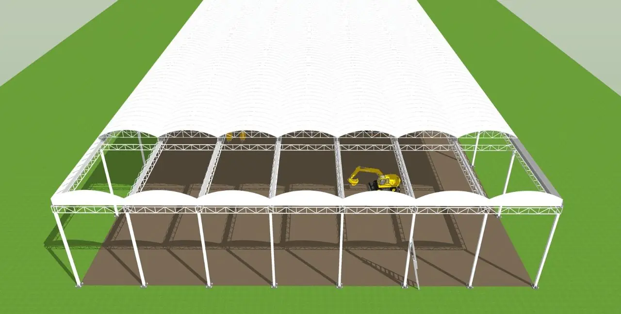 3D design model
In short
Reviewed October 2026
How does a retractable roof open and close?
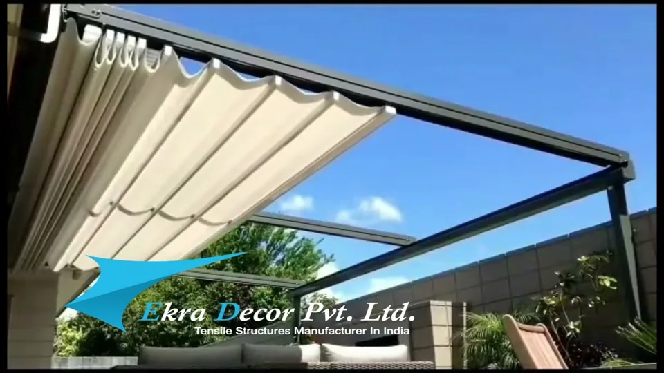
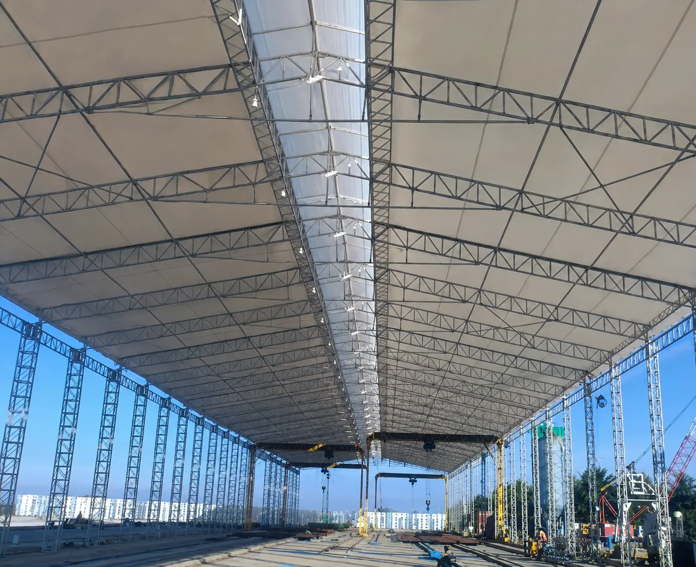
The cover is divided into bays. Each bay sits on a light sub-frame with carriages that ride a fixed rail along the eave. A motor per bay (or a hand drive on small roofs) moves the bays along the rail until they stack at one end; the columns, trusses and foundations never move. On motorised systems, each move starts on an operator command and passes through limit switches, interlocks and an emergency stop.
One structure, three positions
Scroll to open it.
Closed
The membrane bays meet across the opening: full cover from sun and rain.
Part open
Some bays retract toward the parking end. Light and air in, part of the floor still covered.
Open
The bays stack at one end and the floor is open to the sky.
3D model of a five-bay rail-guided system, not a photograph.
Anatomy
Nine parts, one load path.
- 01
Membrane
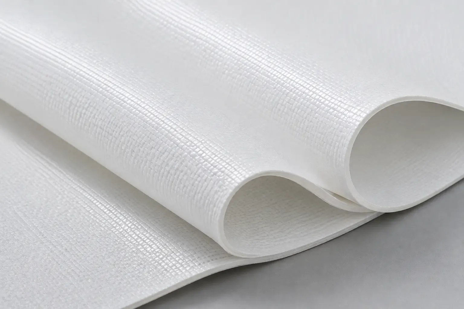
Coated fabric over each bay, detailed to pleat and re-tension through repeated cycles.
- 02
Membrane connection
Reinforced edge, edge cable and clamp profile tie the fabric to the moving frame.
- 03
Moving frame
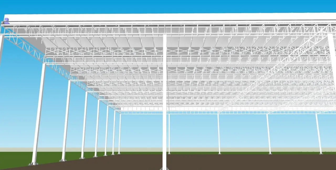
A light steel sub-frame per bay. Rafters carry and tension the membrane.
- 04
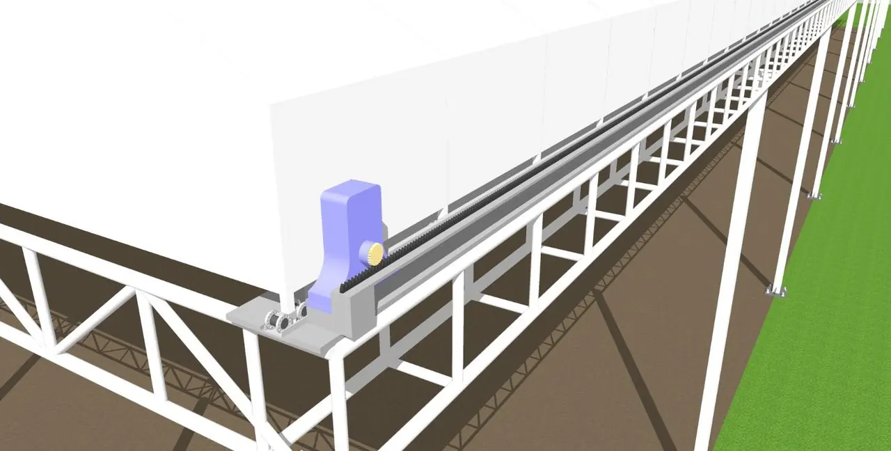
Guide rail
Fixed track along the eave truss: one continuous, aligned travel line.
- 05
Carriage
Roller and track-wheel units that ride the rail and carry the bay into the truss.
- 06
Drive
A motorised unit per bay, travel synchronised across bays.
- 07
Primary steel
Columns, eave lattice trusses and bracing. Fixed, carrying the whole roof.
- 08
Foundation
Column base plate, anchor rods, grout pad and RCC footing, designed per site.
- 09
Controls
Panel, motor controllers, sensors and interlocks that command and monitor every move.
Foundation to roof
Every load follows one path to the ground. The rail and carriage are the only moving link in it.
- 01MembraneSurface load and wind pressure
- 02Moving frameCollects each bay's load
- 03Rail and carriageThe one moving link in the path
- 04Primary steelEave trusses and bracing
- 05ColumnVertical and lateral transfer
- 06Base plate and anchor rodsLoad spread and hold-down
- 07RCC foundationInto bearing ground
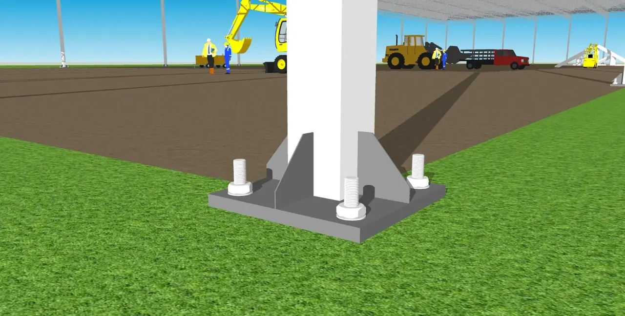
Member sizes, connections and foundations come from project-specific calculation against your site and the applicable codes, including wind loads to IS 875 (Part 3). They are not assumed at concept stage.
Control and safety
Commanded, then monitored.
- Operator command→
- Control panel→
- Safety logic→
- Motor controller per bay→
- Synchronised drive→
- Roof to position
Emergency stop
Halts travel from any operator station, at any point in the cycle.
Limit switches
Stop travel automatically at the open and closed positions.
Mechanical end stops
A physical backup if a limit switch is ever missed.
Motor protection
Halts the drive outside safe load limits.
Safety interlocks
Block conflicting commands across the drive system.
Position monitoring
Keeps every bay in step with the others.
Weather sensors (optional)
Wind or rain triggers a close or hold, where specified.
The final safety design, device selection, redundancy and interlock logic, is project-specific and confirmed at detailed engineering. Manual roofs replace the drive with a chain, crank or push-pull handle and use a manual lock and rubber buffers at the ends.
Only the cover bays and their light sub-frames. The foundations, columns, eave trusses and bracing are fixed and carry the whole roof, moving and stationary, at all times.
Each bay rides on carriages along a fixed guide rail on the eave truss. On motorised systems each bay has its own drive, and the control system keeps travel synchronised and monitors every bay's position.
The barrel-vault curve of each bay sheds rain toward the eave and valley lines, where gutters collect it and carry it clear of the structure. It is designed to drain closed, part open and open.
The roof is designed for the site wind when closed, and the operating guide sets what to do on a storm warning. Wind sensors can be specified to close or hold the roof automatically.
Types
Start a project
Have a site in mind? Send us the size and location.
Tell us where it is, roughly how big, and what it has to cover. We come back with questions, options and the next step, which is usually a site survey.
or call +91 93159 45187